
[Last updated: 02/12/2019]
In this article we will implement a module for opening and closing garage doors and entry gates with a state verification system with Homebridge and Apple Home.
Small demo of the project (English subtitles available) :
At the end of this tutorial it will be possible to you thanks to your iPhone (iPhone, iPad or even your Apple Watch) via the Home app to open, to close or know the state (open, closed, opening, closing) of any device (which will be here called accessory) working in the same way as a garage door or entry gate.
This is the improved version of the plug-in that I introduced in my previous article. The advantage over the previous version is that here we have one code (the plug-in) for the management of different accessories.
Full presentation of the project (English subtitles available) :
Prerequisites for this tutorial: Homebridge installation
1: Necessary material
Most of these items you can find them in your favorite electronics store, or on the internet, on a big auction site, follow my links 🙂
- A Raspberry Pi with Homebridge preinstalled;
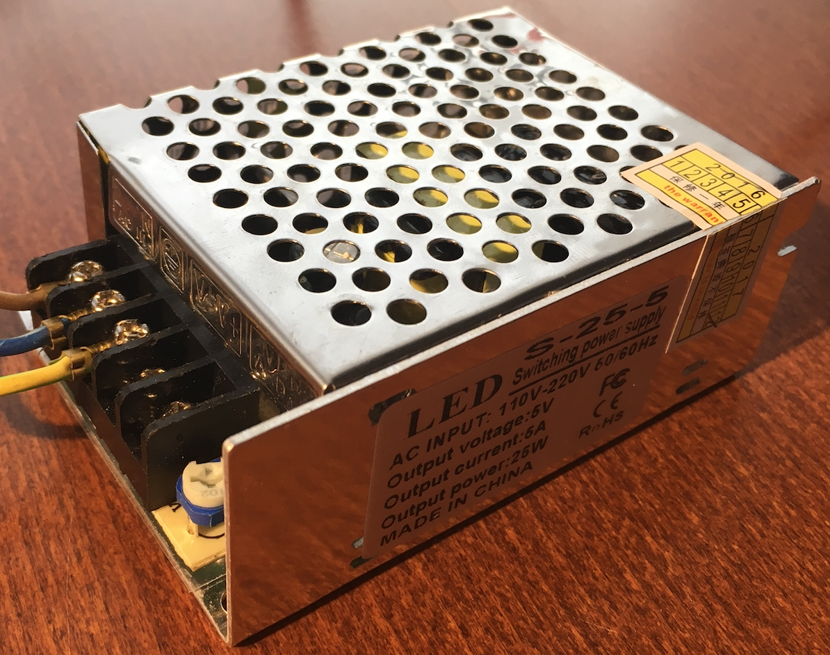
- A power supply of 5v, (available here) personally I took one of 5A 25W;
- A motorized door or gate;
- Pre-formed PCB board (avaiable here);
Then, for each accessory you wish to control, you need the following components. If you want to control a garage door and an entry gate, you will have to double the list of these components, triple if you want to control three accessories, quadruple for four accessories, etc..
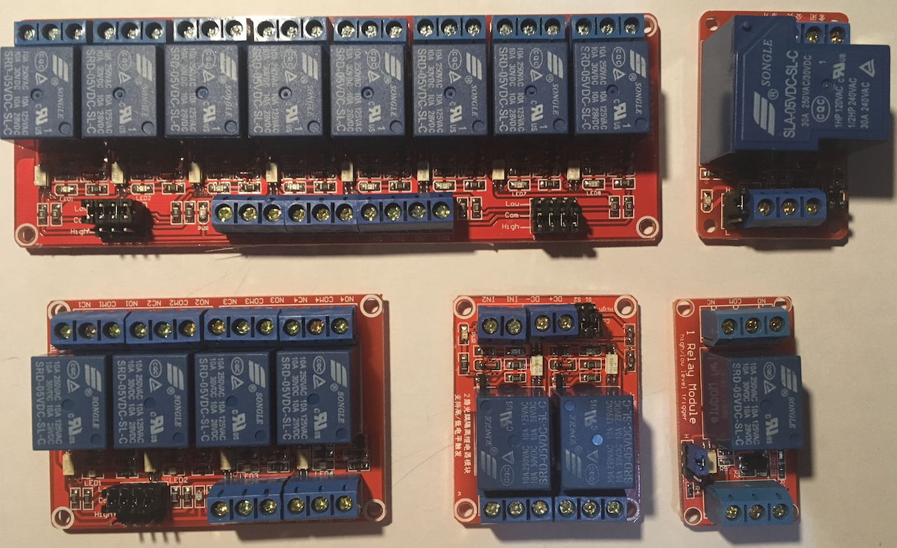
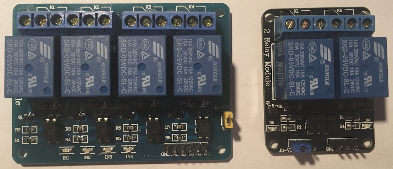
- A Optocoupler module Trigger High (avaiable here) with 1, 2, 4, 8 or 16 relay, depending on the size of your project :). Take Trigger High ou Low AND High relay, but not a simple Trigger Low (see why here at the point “2.1: Comments”);
- Two magnetic sensors;(available here)
- Cables of sufficient length;
- A 150 Ω resistor;
- A 270 Ω resistor;
- Two 1 kΩ resistors ;
- Two 10 kΩ resistors (all resistors avaiable here);
- A optocoupler SFH620A (the schema of this component) available here ;
2: Installation of the plug-in homebridge-garage-gate-opener
2.1: GPIO Initialization
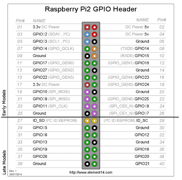
For the garage door, we will use the following connectors :
- GPIO23 (pin 16) : for “SwitchPin”;
- GPIO24 (pin 18) : for “openSensorPin”;
- GPIO25 (pin 22) : for “closedSensorPin”;
For the entry gate, we will use the following connectors:
- GPIO16 (pin 36) : for “SwitchPin”;
- GPIO20 (pin 38) : for “openSensorPin”;
- GPIO21 (pin 40) : for “closedSensorPin”;
“DoorSwitchPin”, “ClosedDoorSensorPin” and “OpenDoorSensorPin” are the names of the connectors used in the code of the plug-in, so we will see what lower in point 2.3.
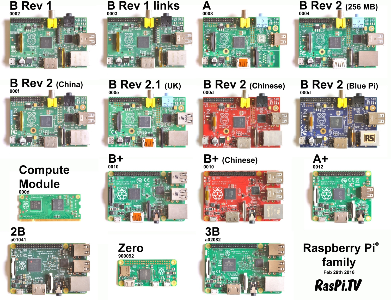
Below, you can see the locations of GPIO of Raspberry Pi 1 Model A +, Raspberry Pi 1 Model B +, Raspberry Pi 2 Model B and the Raspberry Pi 3 Model B, Note that the Raspberry Pi of 1st generation have less of GPIO’s :
So that your GPIO (16, 20, 21, 23, 24 et 25) are initialized at each start of your Raspberry Pi, we must export them, and to do this we will create a script in “/etc/init.d”. Run the following commands :
Enter into the correct directory with : cd /etc/init.d
Create the file for the code by typing : sudo nano exporter-gpio
Paste into this file this CODE. This code exports six GPIO, three for the garage door and three others for the entry gate.
If you want to control only one accessory, your garage door for example, here is the code that you need to paste into this file : CODE. Here only three GPIOs are exported.
Type ctrl+o then ENTER to save your changes, then ctrl+x to exit the editor.
To be sure that this script runs when the Raspberri Pi starting, let’s make a “Daemon”. A “Daemon” is a process that runs as a background task, such as “Services” in Windows.
For that, we will change the rights on this file, type the following command: sudo chmod 755 exporter-gpio.
Then we create a link for the manager of “Demon”, type the following command : sudo update-rc.d exporter-gpio defaults.
We will now execute the program with the command : sudo /etc/init.d/exporter-gpio start, after that, on the screen you should see: [ ok ] Starting exporter_gpio (via systemctl): exporter-gpio.service.
Note: if you already have a GPIO export file and you have just added the code for the new GPIO, you have to restart the daemon with the commands : sudo /etc/init.d/exporter-gpio stop thensudo /etc/init.d/exporter-gpio start replace “export-gpio” with the name of your file.
To ensure that the GPIO are well exported, type the following command ls /sys/class/gpio/ directory, you should see : gpio16 gpio20 gpio21 gpio23 gpio 24 gpio25.
![]()
2.2: Plug-In Installation
Type the following command : sudo npm install -g --unsafe-perm homebridge-garage-gate-opener
Once the installation is complete, you should get a message like this :
![]()
Now that we have installed the plug-in, you have to create an file with extension “.json” which will define our accessories, here our accessories are our garage door and our entry gate. This file needs to be called « config.json » and should be located in the directory ~/.homebridge/config.json.
Type : cd ~/.homebridge.
Then : sudo nano config.json.
Add the following code: CODE. This code creates the accessories “Garage” et “Gate”. If you want to control only one accessory, such as your garage door, here is the sample CODE that you must have.
Adapt the value of OpensInSeconds variables, she must correspond to the time (in seconds) thet your garage door or the gate need to be fully open.
Type ctrl+o then ENTER to save your changes, and ctrl+x to exit the editor.
It is time to test it.
If your Homebridge starts when the Raspberry Pi starts (if it’s a Demon), type the command sudo /etc/init.d/homebridge stop to stop it, then type the command homebridge to restart it.
If everything has been installed and configured correctly, when the Homebridge is started, you should see more or less this :
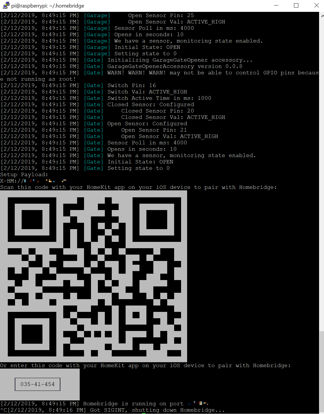
The code that you see on the frame will be used to install our accessory in the Home app of our iDevice (iPhone, iPad, etc.).
At this point, we can conclude that the plug-in is correctly installed and configured on your Raspberry PI.
Press ctrl+c to close Homebridge and proceed to the next point.
3: Finalization and verification of the plug-in
To check that everything works, we will restart the Raspberry Pi sudo reboot now
Once restarted we check if homebridge run correctly : sudo /etc/init.d/homebridge status
You should see a “Running”.
Good work, take a break now 🙂
4: Wiring
In this part we will see how to wire it. A little drawing is better than many words, below you will find a representartion of the concentric to realize, with a Raspberry Pi 1 (mod. B rev. 2) on the left,and a Raspberry Pi 3 on the right :
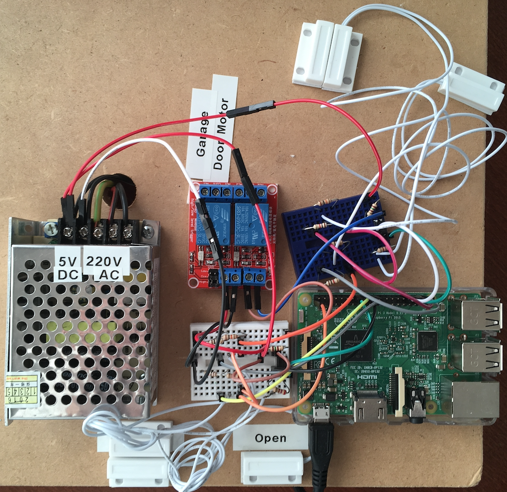
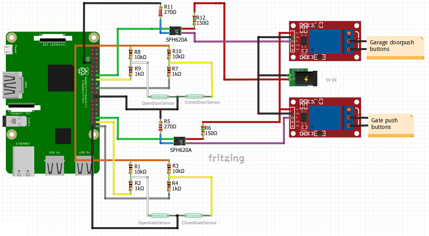
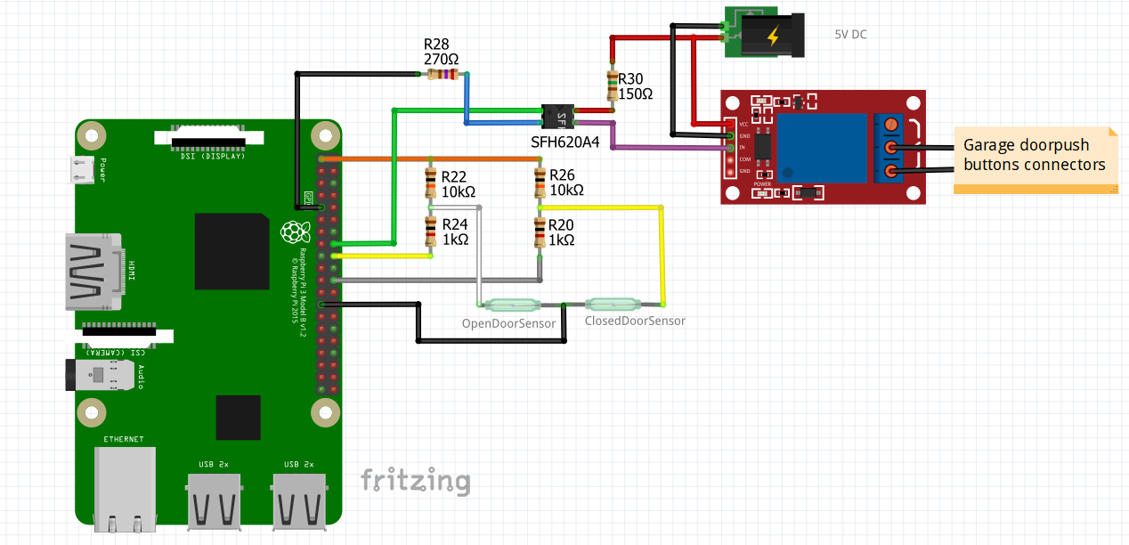
It’s not very clear, a real spaghetti :D. that’s why, below are two schema more clear, the components are not exactly in the same place as on the images above, but the wiring is the same :
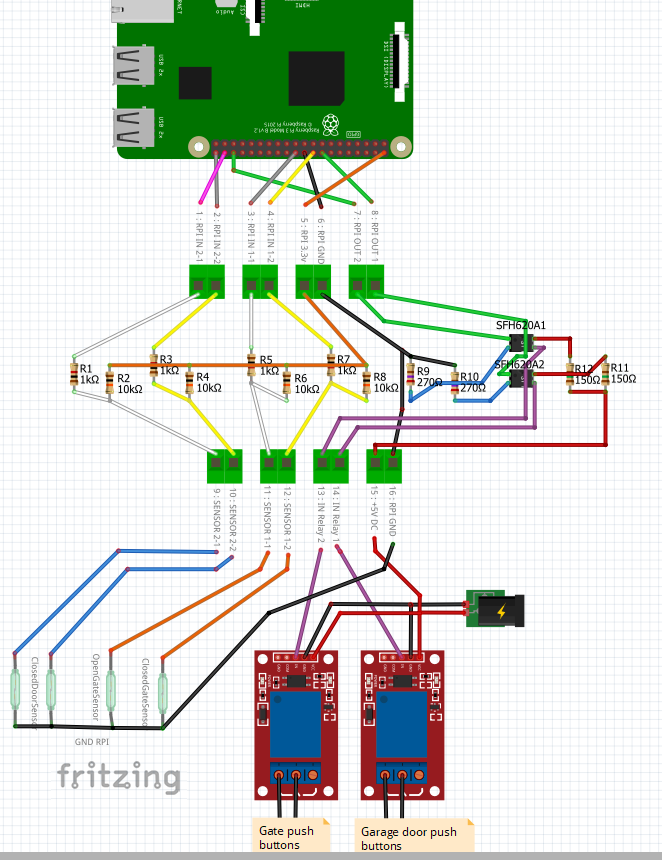
Wiring for a garage door and an entry gate :
Wiring for only one accessory, for example a garage door :
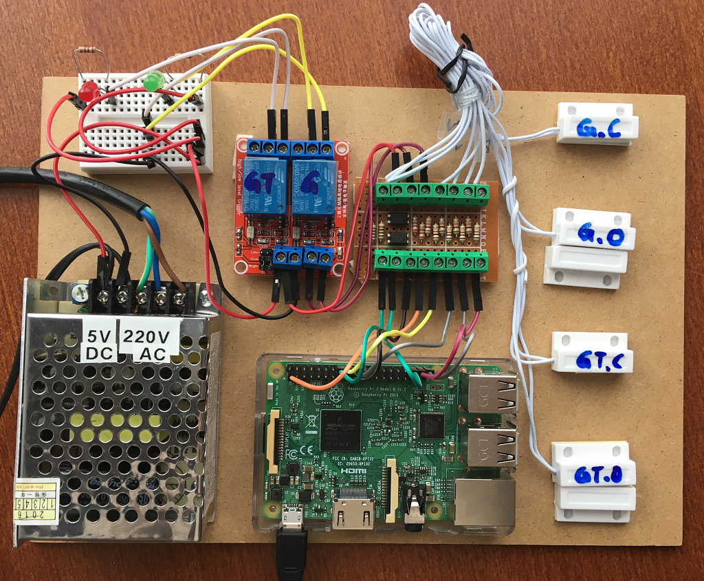
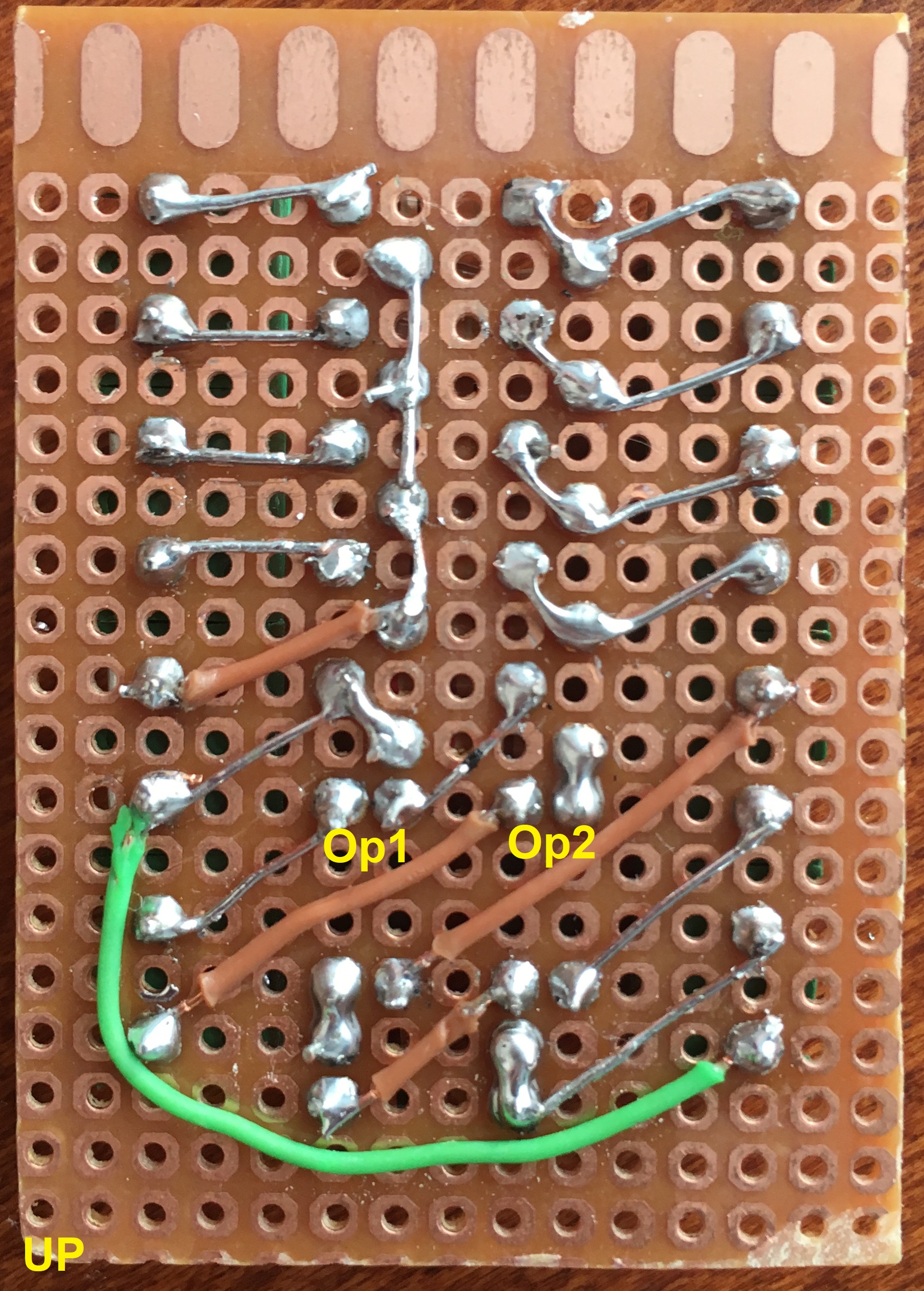
In practice, here is my realization on my test board :
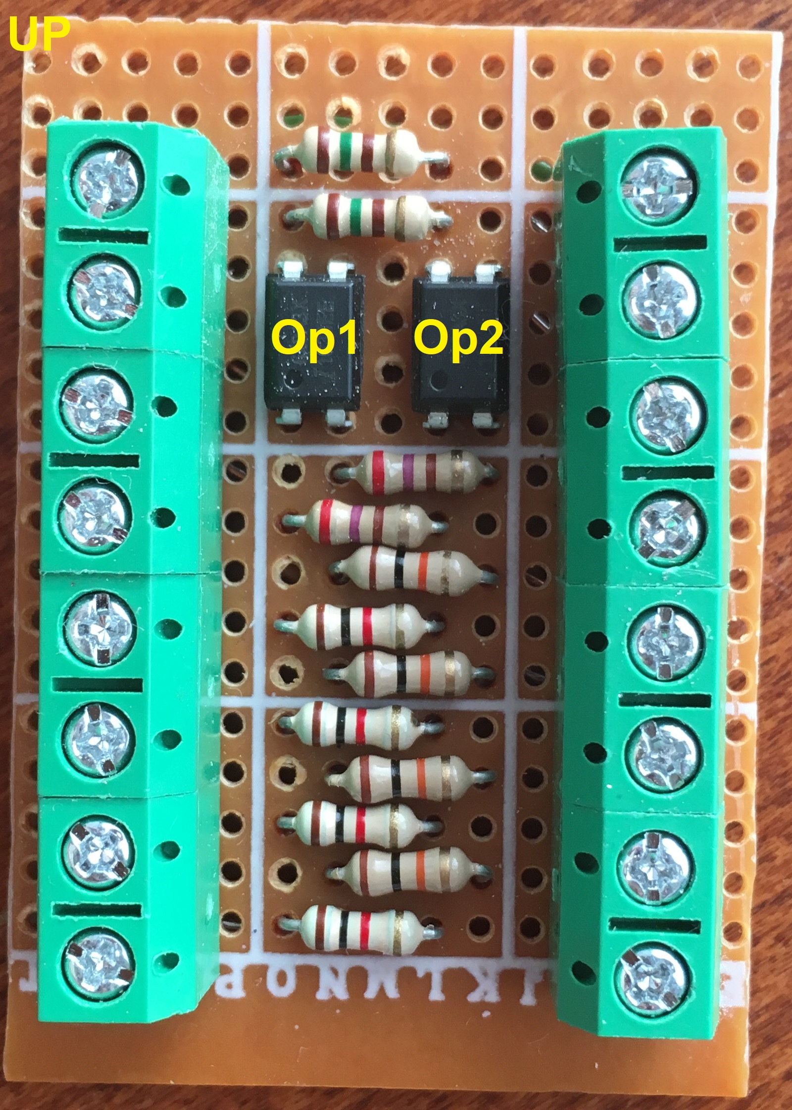
Here is the wiring that I made on the PCB board:
Now it’s your turn 🙂
Once the wiring is completed, Add your new accessory in the Home app.
If you liked it, feel free to share this article.
Thank you and see you soon for other projects.
Hi, Where can I find the package (to delete on npm and doesn’t exist on MForge) Thanks
Hi Xavier,
Sorry to answer you so late, I am very busy with other projects.
There was an error in my tutorial, It’s fixed now. I am sorry for the problem that this caused you. 🙁
The command was not : sudo npm install -g –unsafe-perm homebridge-rasppi-garagegateopener
but : sudo npm install -g –unsafe-perm homebridge-garage-gate-opener
Here is the link of the package.
As soon as I have a moment I will test all to be sure that all is OK.
Courage for your project 🙂
Hi
Thanks
I use it finally but don’t make the link with previous name….
Could I ask for an improvement (my node hs knowledge is too poor) ?
My gate door auto close after few seconds
Is it possible to have an evolution for this ?
Regards
Xavier,
You would like that your gate stay open ?
My gate also closes automatically, but it doesn’t come from the Homebridge.
The Homebridge is just giving the opening impetus, and if within X seconds the motors don’t receive a second impulsion, they close automatically.
The motherboard of my gate motors is programmed to close automatically after 20 seconds.
So after opening, if I want to keep my gate opened, I must program it in the motherboard of my gate motors.
I hope that this helps you 🙂
Hi,
No but as I have no sensor I want HomeKit/Homebridge to have the good state
Actually gate auto closed and Homebride say Open !
My idea was to write at end of setFinalDoorState a sleep, set state to Closed (settings in .json)
Regards
Xavier
OK, now I clearly understand your request 🙂
Now I’m busy on two big project that will still take me several weeks but when I’ll have more time I will come back to this project and keep you informed.
See you soon.
Hi,
In your tuto you said “but not a simple Trigger Low (see why below in article);”
But I can’t find the reason in the article
I manage to make it work (no resistance …) with a TriggerLow item.
My only issue is when I have power outage or Rasp Pi reboot (doors open !)
Does yours do the same or is it the resaon of resistance optocoupler ….
Merci
You absolutely need a relay Trigger High, I explain it briefly in the point “2.1: Comments” in THIS article.
It is possible to turn a relay Trigger LOW into Trigger HIGH, but I have not done it personally, and I can not find the link of the tutorial to do it 🙁
I do not have this problem because I use the GPIO which remain at 0 when the Raspberry reboot, and I use Trigger High relays.