
In this article we will implement a module of opening/closing of a garage door with a system of State verification.
Prerequisite for this tutorial : Homebridge installation
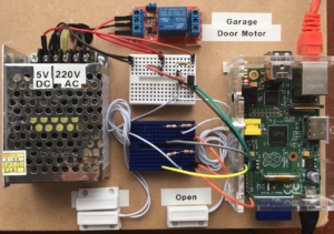
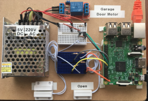
When this system will be mounted on my garage door I’d do a video, for now, here is a the installation on my test Board:
1: Necessary material
Most of these elements you can or find them at your preferred electronics store, or on the internet, follow my links 🙂
- A Raspberry Pi with preinstalled Homebridge;
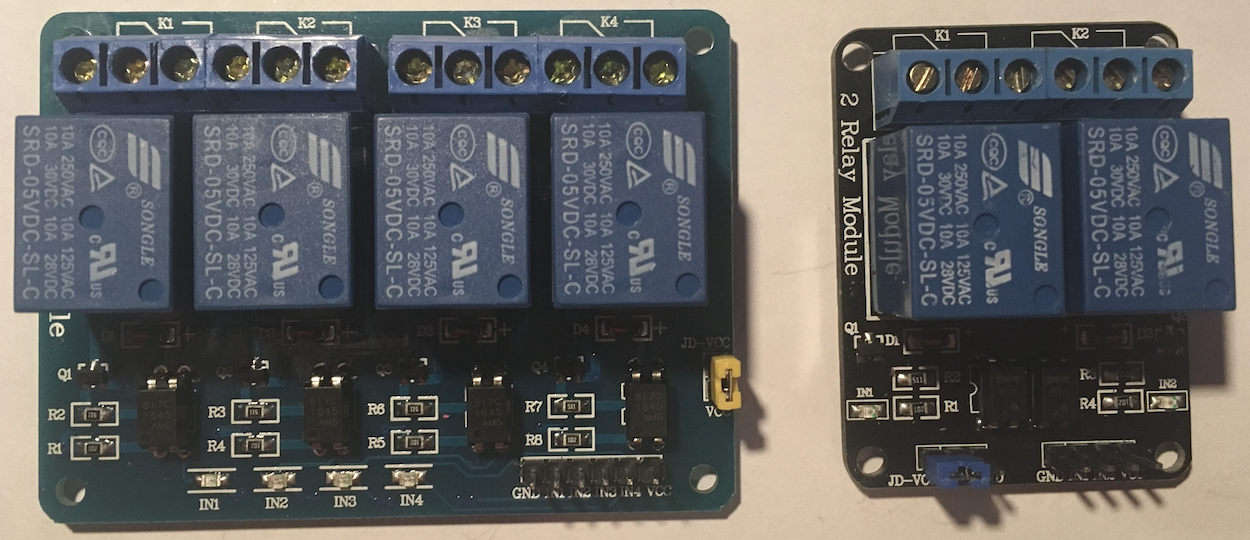
- A optocoupler module Trigger High avec 1, 2, 4, 8 ou 16 switches, depending on the scope of your project. Take Trigger high or Low and High switches, but not a simple Trigger Low (see why below in article);
- Two magnetic sensors (Available here);
- Cables of sufficient length;
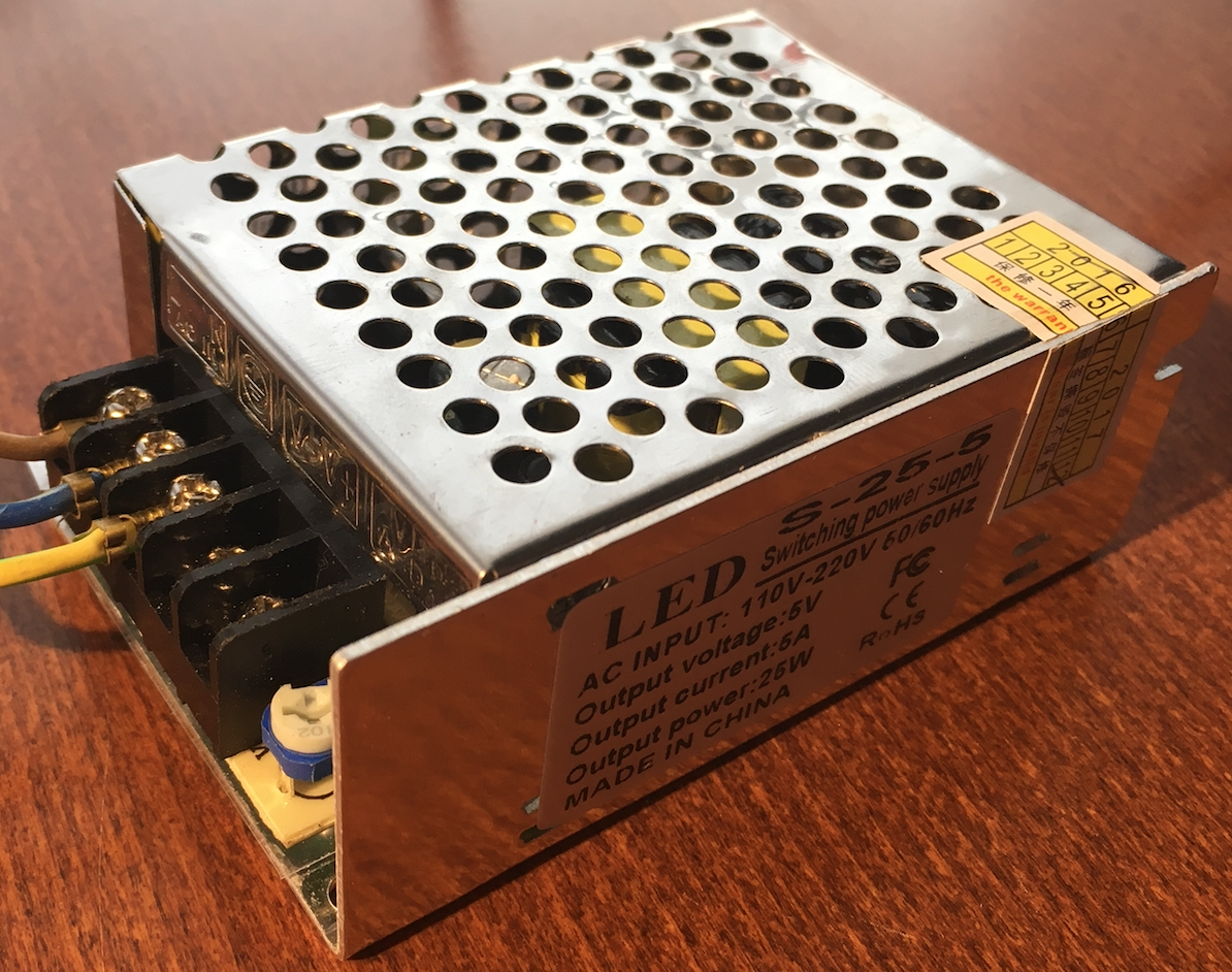
- A 5v power supply (available here), Personally I took a 5A 25W, but one of 2A is more than enough for this little project;
- A 150 Ω resistor;
- A 270 Ω resistor;
- Two 1 kΩ resistors ;
- Two 10 kΩ resistors (all resistors available here);
- A optocoupler SFH620A (the schema of this component) available here ;
- And a garage door with a motor;
2: Installation of plug-in GarageDoor
We’ll use the code already created by a generous (Pojo) programmer who puts it on the site NPMJS and GitHub.
2.1: Comments
2.1.1 : On the his plug-in page, Pojo indicates that at the start of the Raspberry Pi (model 1 I suppose), some GPIO (General Purpose Input/Output) go to State 1, which may well cause problems during power cuts, Imagine : A power failure occurs in your home, when the power comes back, the Raspberry Pi restarts, and without asking anyone, your garage door opens… it might be very problématique..
The GPIO to avoid are the following:
- GPIO0/2
- GPIO1/3
- GPIO4
- GPIO7
- GPIO8
I admit not having tested it, that’s why at first I will not use them, and if later I have to use one of those, I’d do more tests.
2.1.2 : We have to create and edit files, here is a small list of the commands that we would use :
- Opening or creating the file with an text editor, with “Super User” rights :
sudo nano myFile - Saving the modifications :
ctrl + o - Close the text editor :
ctrl + x
I use the editor “nano” but there are others like: VI, VIM, etc… so use whichever you prefer.
2.2: GPIO initialization
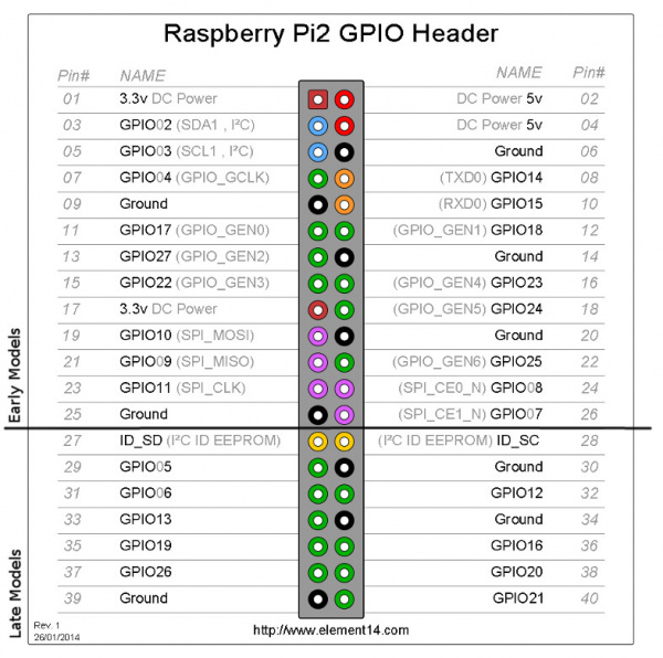
So we will use the following connectors :
- GPIO23 (pin 16) : pour le “DoorSwitchPin”
- GPIO24 (pin 18) : pour le “OpenDoorSensorPin”
- GPIO25 (pin 22) : pour le “ClosedDoorSensorPin”
“DoorSwitchPin”, “ClosedDoorSensorPin” and “OpenDoorSensorPin” are the names of the connectors used in the code of the plug-in, so we will see what lower in point 2.3.
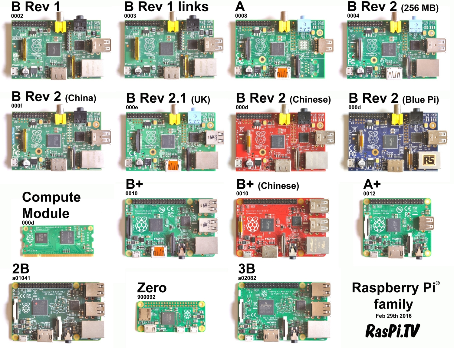
Below, you can see the locations of GPIO of Raspberry Pi 1 Model A +, Raspberry Pi 1 Model B +, Raspberry Pi 2 Model B and the Raspberry Pi 3 Model B, Note that the Raspberry Pi of 1st generation have less of GPIO’s :
So that your GPIO (23, 24 and 25) are initialized at each start of your Raspberry Pi, we must export them, and to do this we will create a script in “/etc/init.d”. Run the following commands:
cd /etc/init.d
sudo nano garage-door-gpio
Paste this code in this file : Adapted code of Pojo.
Then type ctrl+o to save and then ctrl+x to exit the editor.
I adapted the code of Pojo because it lacked the export of the GPIO25 for the ‘open’ door detector.
To be sure that this script runs when the Raspberri Pi starting, let’s make a “Daemon”. A “Daemon” is a process that runs as a background task, such as “Services” in Windows.
We will change the rights on this file : sudo chmod 755 garage-door-gpio
Then we created a link for the “Daemon” Manager : sudo update-rc.d garage-door-gpio defaults.
We will now run the program with the command : sudo /etc/init.d/garage-door-gpio start, as result, on the screen you should see: [ ok ] Starting garage-door-gpio (via systemctl): garage-door-gpio.service.
To ensure that the GPIO are well exported, type the following command ls /sys/class/gpio/ directory , you should see : gpio23 gpio24 gpio25.
![]()
2.3: Plug-in installation
We install the plug-in of Pojo : sudo npm install -g homebridge-rasppi-gpio-garagedoor
Once installation is complete, you should get a message like this :
![]()
Now that we have our first installed plug-in, we need to create a file with extension “.json” who defines our accessories, here, our accessory is our “Garage door”. This file needs to be called « config.json » and should be located in the directory ~/.homebridge/config.json.
Type : cd ~/.homebridge.
Then : sudo nano config.json.
Add the following code : CODE;
Adjust the value of the doorOpensInSeconds variable that should correspond to the time (in seconds) needed for your garage door to be open.
Type ctrl+o then ENTER to save your changes, and ctrl+x to exit the editor.
It is time to test it.
If your Homebridge starts when the Raspberry Pi starts (Daemon), type sudo /etc/init.d/homebridge stop to stop it, and then type homebridge to restart it.
If everything has been installed and configured correctly, when the Homebridge is started, you should see this :

The code that you see on the frame will be used to install our accessory in the Home app of our iDevice (iPhone, iPad, etc.).
At this point, we can conclude that the plug-in is correctly installed and configured on your Raspberry PI.
Press ctrl+c to close Homebridge and proceed to the next point.
3: Finalization and verification of the plug-in
To check that everything works, we will restart the Raspberry Pi :sudo reboot now
Once restarted we check if homebridge run correctly : sudo /etc/init.d/homebridge status
You should see a “Running”.
Good work, take a break now 🙂
4: Wiring
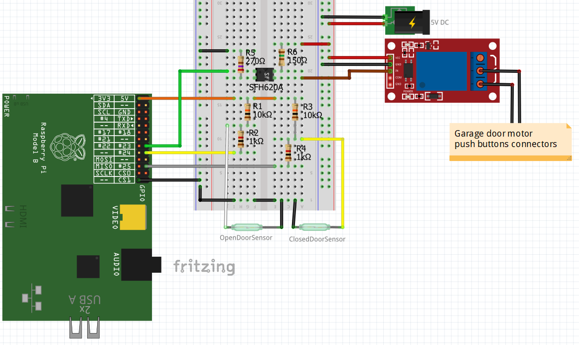
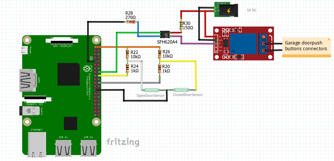
In this part we will see how to wire it. A little drawing is better than many words, below you will find a representartion of the concentric to realize, with a Raspberry Pi 1 (mod. B rev. 2) on the left,and a Raspberry Pi 3 on the right :
OK, OK, It’s is not very clear 😀 , that’s why, below are two schema more clear, the components are not exactly in the same place as on the images above, but the wiring is the same :
Version without testing Board :
Now it’s your turn 🙂
Once the wiring is completed, Add your new accessory in the Home app.
Feel free to share this article.
Hi. Thank you for a really good guide. I have build a complete replica of your setup and it works great. I did find one small mistake though. your +5v and ground has to be switched for the optocoupler to work.
Hi, Andreas, I’m very happy that my tuto helped you 🙂
If I good understand, you want to send Ground to the IN pin of the relay board when the optocoupler SFH620A is powered ?
Yes. Following your link I purchased an Optocoupler called PC817C. It should be connected as shown on this picture: https://http2.mlstatic.com/D_Q_NP_898421-MLB20782117133_062016-Q.jpg
Anode(1) = +5V
Cathode(2) = Ground
OK, now I understand. My optocoupler is a SFH620A, here is his schema, that’s why my wiring works.
But in the case of a PC817C you are 100% right, that’s why I adapted my wiring schema 🙂
Thank you.
Hi! Thanks for the well written guide. Though I have one problem. When I am closing my garage door, and it gets obstructed on the way down, it won’t go fully up again, so that it is half way open. The magnet therefore doesn’t touch one of the sensors but in the app, it still says that my garage door is closed. Is there a way to change the initial stage of the garage door from closed to open? Or can you think of another solution?
Thanks in advance
Hi, when your door is blocked (not completely closed or fully open), and when the app shows that the door is closed, if you restart the app, doesn’t it show a indeterminate status of the door ?